

Beam shaping optics (Dr. Arndt Last)
Contact: Dr. Arndt Last, phone: +49 721 608-23817, arndt last ∂does-not-exist.kit edu
X-ray prism lenses (XPLs) and Fresnel lenses can be used for illumination purposes in the hard X-ray wavelength regime as they are used in visible light regime. We develop polymer lenses for certain applications in full-field X-ray microscopy and other imaging techniques.
Condenser
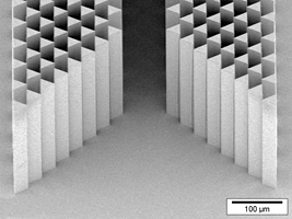
The sample illumination in a full-field microscope application should fulfil three requirements. First, the overall transmission of the condenser should be high. This is achieved by using thousands of refracting micro prisms with edge lengths in the tens of micrometre range. In this way the ratio of refracting surfaces to absorbing bulk material is optimized. The production challenge is the high aspect ratio of such micro prisms. In this project we develop condensers fabricated via deep X-ray lithography. Second, the intensity in the sample plane shall be homogenous across the whole field of view. And third, the rays coming from the illumination optics shall be accepted by the objective lens.
X-ray prism lens
Beam shaper
At high brilliance synchrotron sources the beam size is limited by the low divergence of the beam from the undulator source in vertical direction. This relatively small beam cross section limits the available field of view for full-field imaging. For many applications a larger field of view is desirable e.g. for medical, or biological samples or in materials science where the sample size is given by the manufacturing process. To cover long samples, several height steps are scanned and the tomograms are stacked, which is time consuming. Furthermore, the Gaussian-shaped beam profile is not ideal for full-field imaging where a more constant intensity over the sample would be advantageous.
To overcome these limitations we developed refractive beam shaping optics, produced via deep X-ray lithography using SU-8, a radiation stable epoxy based polymer. The designed optics consist of biconvex Fresnel-elements defocusing the beam. The local curvature is tailored to widen the incoming beam and at the same time change the incident Gaussian-like beam profile to a top-hat intensity distribution.
When testing the beam shaper at the P05 beamline of PETRA III (Hamburg, Germany) operated by HZG, we were able to widen up the original beam profile in vertical direction from 1.9 mm to 6 mm. Due to the fact that we are free to shape the facet of the lens for a certain purpose, it is possible to generate any desired intensity distribution with a suitable designed beam shaper of this type.
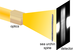
Setup with beam widening optics and a sea urchin spine as sample
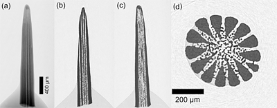
Tomography of a sea urchin spine using the beam shaper setup:
absorption image (a) and reconstructed tomographic slice (b) to (d)
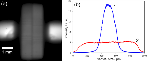
Left: Image of beam profile at P05, with beam shaping optics widening the beam.
Right: Beam profile changes from Gaussian-like (1) to more top-hat like distribution (2).
Liquid X-ray lens (Josephine Gutekunst)
Contact: Josephine Gutekunst, phone: +49 721 608-22786, josephine gutekunst ∂does-not-exist.kit edu
A drawback of Compound Refractive X-ray Lenses (CRLs) made from polymers is their limitation to be used only in a monochromatic beam at synchrotron sources. As the thermal heat conduction coefficient of polymer is low, the power of a white beam would heat up the CRL too much and destroy it. In this project we develop a CRL, where a liquid is pressed through nozzles with double parabolic cross section. The jets formed are used as line focussing lens elements when X-rays pass perpendicular to the liquid jets.
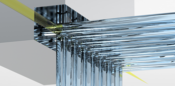
Principle of refractive liquid X-ray lenses (yellow the X-rays passing the point focus lens)
Further activities (Dr. Arndt Last)
Contact: Dr. Arndt Last, phone: +49 721 608-23817, arndt last ∂does-not-exist.kit edu
Optics with an easily adjustable focal length will serve X-ray microscopy a lot. An X-ray zoom lens renders the possibility to freely choose the magnification factor in full-field microscopy without moving the objective lens. The distance between sample and image plane can be kept constant even when changing the photon energy. With such optics even X-ray spectroscopic measurements can profit, as in spectroscopy changing the energy is inherent in the method.
At IMT Compound Refractive X-ray Lenses (CRLs) have been developed. These lenses show good optical properties in the hard X-ray regime for photon energies above about 8 keV up to about 100 keV. Until now several customized lens layouts for applications are processed on one substrate. So one can select the most suitable lens, shift it into the beam, slightly readjust the system and use the lens. To achieve an adjustable focal length single lens elements have to be moved out and back into the beam. Therefore in this project we use piezo bender actuators to bend previous sawed substrate stripes carrying lens elements at the end out of the optical path and precisely and reversibly back into the beam. This so called X-ray Zoom Lens (XZL) is remote-controlled.
Principle of an X-ray zoom lens – single lens elements moved in and out of the beam

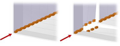
Radiography of a point focus X-ray zoom lens with lens elements in (left)
and out of the beam (right)
In comparison to a transfocator with a focal length in the meter range, an X-ray zoom lens can provide focal length in the centimetre to meter range. The zoom lens has a small overall size and can therefore easily be mounted in different beamlines. It allows for fast switching the focal length. Therefore we are always looking for new application and measurement methods where these new possibilities can be used.

Mounted piezo driven point focus X-ray zoom lens
Multi focus lens
Due to absorption in the lens material, the aperture of Compound Refractive X-ray Lenses (CRLs) is absorption limited, and so is the numerical aperture. When using CRLs for full-field microscopy at laboratory sources, most of the large-angle radiation from the sample is lost. The basic idea of this project is to overcome this by using an array of CRLs with slightly tilted optical axes, which intersect in one point in the sample plane. By imaging the same field of view from slightly different directions, the exposure time can be reduced drastically. In principle the photon flux on the detector could be increased by a factor of n2-1 with an n x n multi-focus CRL.
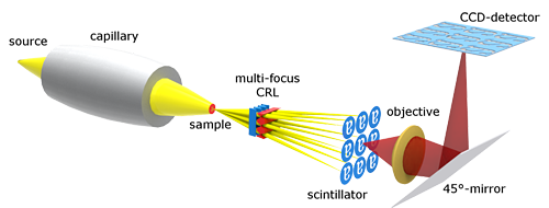
Working principle of multi-focus CRLs: The sample is imaged by an array of CRLs (here 3 x 3) with slightly tilted optical axes. The resulting nine images of the same field of view are detected indirectly via a scintillator (X-rays: yellow; VIS: red). The capillary acts as an illumination optics, which is necessary for full-field microscopy at micro focus sources.
Hyperresolution gratings (Dr. Martin Börner, Dr. Pascal Meyer)
Contact:
Dr. Martin Börner, phone: +49 721 608-24437, martin boerner ∂does-not-exist.kit edu
Dr. Pascal Meyer, phone: +49 721 608-23924, pascal meyer ∂does-not-exist.kit edu
The spatial resolution attained by grating based interferometry is limited by the grating period. This limitation can be overcome by making use of the self-imaging effect caused by a shaped grating and a sub-period object scan. With the shaped grating periodic intensity spots with sizes of less than 1 µm can be generated resulting in spatial resolution below one micron in the object scan. The FoV can be in the square centimeter range due to the capability to fabricate either high aspect ratio gratings with several centimeter lengths or by fabricating 2D shaped gratings on areas of several centimeters by several centimeters. Also high-energy X-rays (even over 30 keV) can be made available with this concept to observe thick samples. Hyper resolution X-ray imaging has a lot of applications; for example, in the observations of
- Voids in the circuit board or mold of ICs,
- Discharge-induced micro cracks in polymer insulators,
- Damage in solar cells after long-term use,
- Micro-defects in carbon fiber reinforced plastic (CFRP),
- Micro-contamination of alumina powder in aluminum metal sheet, and so on.
This activity is part of the Momose ERATO (Exploratory Research for Advanced Technology) phase imaging project funded by JST (Japan Science and Technology Agency) and of the 2 by 2 BMBF projects HyReXPhI (Martin Börner, martin boerner ∂does-not-exist.kit edu). It is also part of the PhD theses of Talgat Mamyrbayev (PhD dissertation Talgat Mamyrbayev, "Development of pixel super-resolution scanning transmission X-ray microscopy for material science") und Pouria Zangi (pouria zangi ∂does-not-exist.kit edu).
This project requires:
- Geometry optimization of the grating lamella using Talbot carpet simulation
 |
 |
|
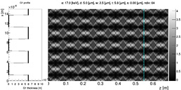
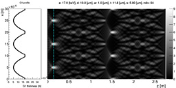
| Simulated Talbot carpet for a rectangular shaped phase grating with intensity profile (π phase shifting, Ni thickness 5.92 µm) |
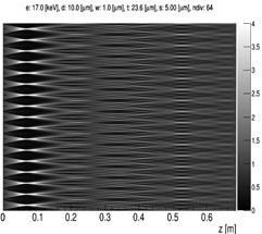
Simulated Talbot carpet for a parabolic shaped phase grating with intensity profile (2π phase shifting, Ni thickness 11.84 µm) |
- Development of processes to fabricate 1D and 2D gratings with modified gratings lamella geometry and heights of more than 200 µm for large FoV in absorption and phase contrast imaging
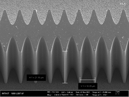 |
| Parabolic phase gratings fabricated by x-ray LIGA technology: biconcave shaped lamellae (period: 10 µm, DC: 0.1, lamella thickness: 23.64 µm). |
- Characterization of new geometry gratings at synchrotron beamlines like those at KARA or Spring-8.
 |
 |
|
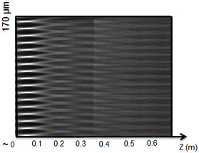
| Simulated Talbot carpet for 4π biconcave phase grating, DC 0.1 | Measured Talbot carpet for 4π biconcave phase grating, DC 0.1 |
- X-ray imaging experiments to identify the advantage of the new concept in absorption and phase contrast.
Gratings fabrication and characterization (KNMFi projects, Dr. Pascal Meyer)
Contact: Dr. Pascal Meyer, phone: +49 721 608-23924, pascal meyer ∂does-not-exist.kit edu
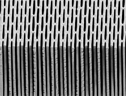
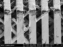
High quality absorption gratings, are fabricated routinely for energies up to 30 keV with heights of 50 µm to 70 µm using deep x-ray lithography. Phase gratings are fabricated with continuous lamellas out of nickel or gold. Shifting to higher energies, most interesting in materials analysis, the fabrication of absorption gratings, in particular G2, becomes challenging: the absorbing grating lamellas must be high enough to fully absorb the high energy X-rays (e.g., to absorb 90% of 100 keV X-rays, the gold thickness has to be 230 µm). In addition, the period needs to be small (2-5 μm) to ensure high sensitivity of the system.
It is our goal to improve the gratings quality with focusing on the following issues:
- reproducibility of the process,
- downsizing the period and increasing the resist/metal thickness by modifying the photoresist sensitivity and contrast,
- increasing the mechanical stability by finding the best combination of applied dose and post exposure bake (PEB), by using freeze drying and room temperature electroplating,
- minimizing the secondary radiation by using low Z electroplating layer/substrate like graphite,
- optimizing the design and the gratings geometry to obtain the minimum possible deviation from an ideal grating.
 |
 |
|
| a) | c) | |
 |
 |
|
| b) | d) |
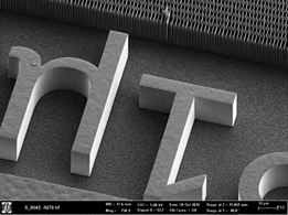
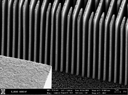
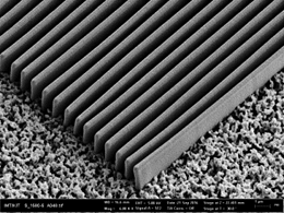
a) 4.8 µm period gratings 200 µm high after development
b) after electroplating and removing the resist
c) 10 µm period gratings 250 µm high after development, the +/- 30° pillar could be seen
d) 4.8 µm period 150 mm thick after electroplating and removing the resist, resist pillar leads to a hole in the final electroplated structure
Further Activities (Dr. Pascal Meyer)
Contact: Dr. Pascal Meyer, phone: +49 721 608-23924, pascal meyer ∂does-not-exist.kit edu
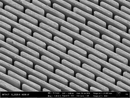
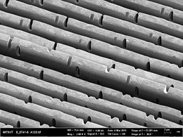
Differential phase contrast imaging today can rely only on gratings with periods > 4.8 µm. For building X-ray imaging set-ups of less than 1 m with acceptable resolution it is necessary to push the limits of grating periods. The resolution of the acquired X-ray images depends strongly on the quality and aspect ratio of the X-ray gratings which requires the use of X-ray lithography to fabricate gratings with periods less than 2µm and heights of more than 50µm.
 |
 |
|
 |
 |
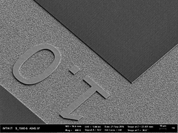
1 µm period gratings (left: “bridge design” absorption gratings; gold thickness: 20 µm;
right: long lamellae phase gratings; nickel thickness: 3 µm)
The fabrication of sub-µm gratings is challenging and involves several parameters in the entire fabrication process. The quality of such sub-µm gratings strongly depend on the stability of the resist template with continuous lamellas, which can suffer from shrinkage, bending and sticking during fabrication. This becomes more critical with decreasing structural widths. The exposure and development conditions can also generate variations in the outcome, and also physical effects on the nanometer level like photo-electron penetration.